Computer networks form the foundation that connects the digital world – from sending messages and browsing the web to operating cloud services. For diverse devices, software, and protocols to “understand” one another, the industry needs a structured approach to describe how data is transmitted and processed. The OSI (Open Systems Interconnection) model was created as a conceptual map that helps separate and standardize networking functions into clearly defined layers. In this article, you and I will explore each layer of the OSI model, gain a clear understanding of its functions, real-world examples, how the layers interact, and the role of OSI in both learning and practical applications.
1. Overview of the OSI Model
The OSI (Open Systems Interconnection) model was developed by the International Organization for Standardization (ISO) in the early 1980s with the goal of creating a common standard to describe how different computer systems communicate over a network. Before OSI, each manufacturer often used its own proprietary protocols, making interconnection between systems complex and lacking compatibility. The introduction of OSI provided a “common language” that allows all devices and software to understand and exchange data with one another, regardless of who developed them.
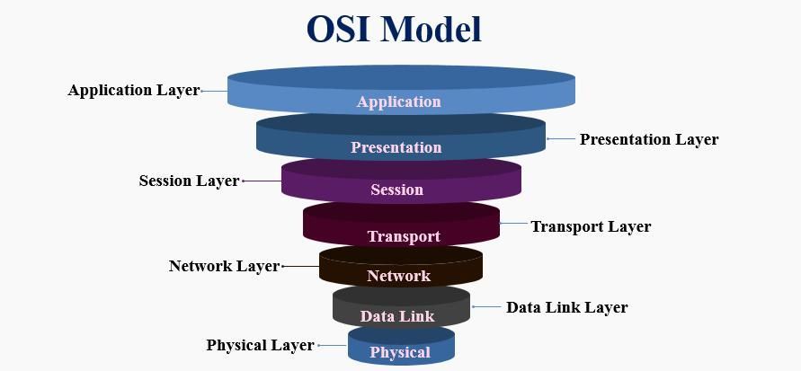
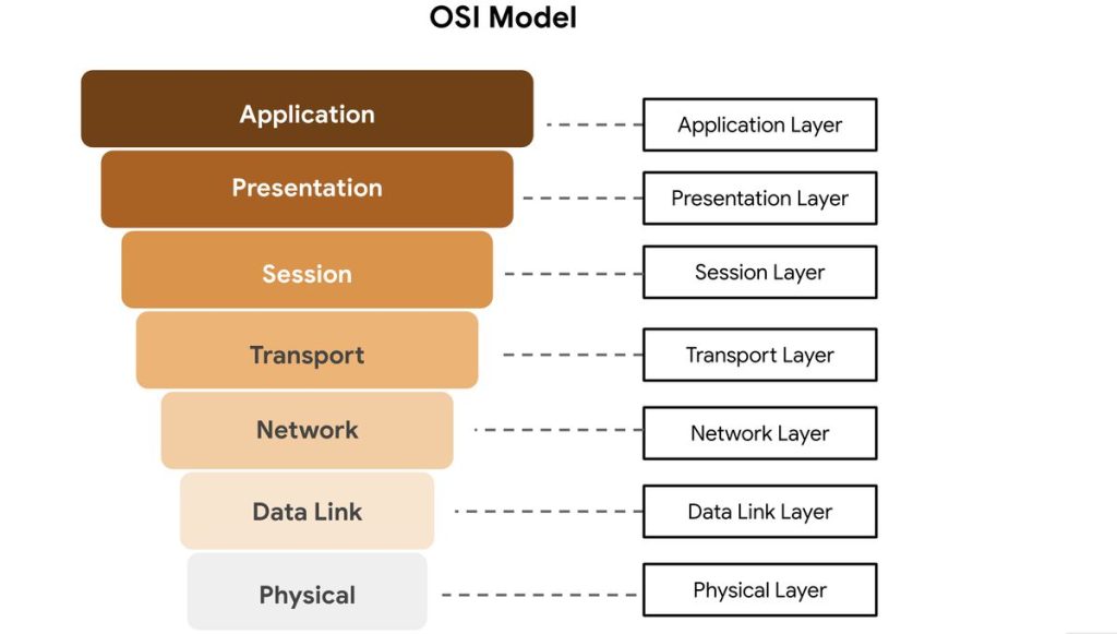
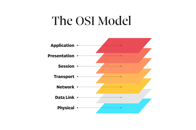
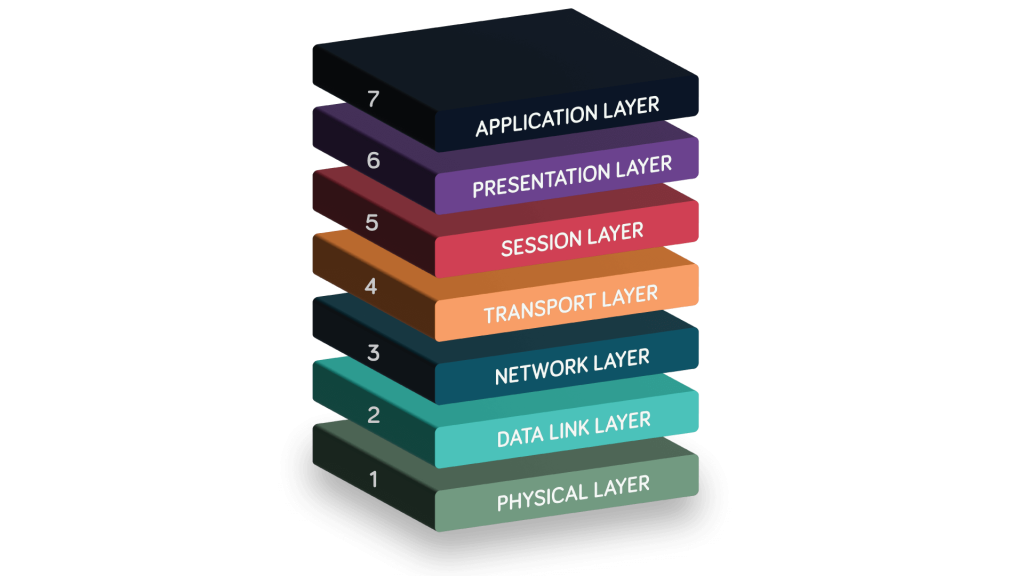
The OSI model consists of seven layers, arranged from the Physical Layer at the bottom – where data is transmitted as electrical signals or waves – up to the Application Layer at the top, where user-facing programs such as web browsers or email applications operate. Each layer performs a specific role in the data transmission process and communicates with the layer above and below it through standardized interfaces. As a result, designing, upgrading, or modifying one layer does not directly affect the others, making the system more flexible and easier to scale.
Why Is the OSI Model Necessary?
Without a standard model, building and operating networks would become chaotic: each company would define its own method of data transmission, leading to incompatibility, difficult maintenance, and challenging fault detection. The OSI model addresses these issues by dividing the networking system into clearly defined components, allowing us to:
- Break problems into smaller parts: Easier to manage and develop, with each layer focusing solely on its own responsibilities.
- Simplify troubleshooting: When a network issue occurs, it is easier to identify which layer is responsible – for example, cable problems belong to the Physical Layer, while IP or routing issues reside in the Network Layer.
- Enable structured learning and research: Learners can progress from simple concepts (bits, frames, packets) to more complex ones (session, presentation, application).
- Standardize communication across vendors: Thanks to OSI, devices from Cisco, Huawei, or Juniper can operate together using standardized protocols.
In summary, the OSI model is not merely a theoretical concept, but a standardized conceptual framework that helps us gain a deep understanding of how data moves within a network. By mastering the OSI model, we can “read” the data flow, quickly pinpoint the location of faults, and design more effective network systems.
2. Functions and Roles of Each Layer in the OSI Model
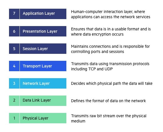
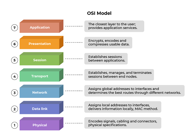
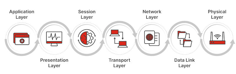
The OSI model divides the networking system into seven layers, from the physical layer to the application layer, with each layer handling a distinct part of the data transmission and processing process. Understanding each layer enables network engineers to more easily identify issues, optimize performance, and design standardized network systems. Below is a detailed explanation of each layer:
2.1. Physical Layer
The Physical Layer is the lowest foundation of the OSI model. It is responsible for transmitting data in the form of bits (0s and 1s) between devices through physical media such as copper cables, fiber-optic cables, or radio waves. In other words, this layer converts logical data into electrical, optical, or wireless signals so that it can be transmitted in the real world.
This layer does not concern itself with the meaning of the data; instead, it focuses solely on whether the data is transmitted correctly at the physical level. It defines technical characteristics such as:
- Voltage levels and signaling: The voltage levels that represent bit 0 and bit 1, signal waveforms, and timing between bit transitions.
- Data transmission rate (bit rate): The speed at which data is sent, measured in bits per second (bps).
- Connectors and physical interfaces: Connector standards such as RJ45, USB, SC/LC (fiber optic).
- Transmission modes: Full-duplex, half-duplex, or simplex communication.
- Distance and signal attenuation: Maximum cable length, resistance to interference, and signal strength to ensure data is not distorted or lost.
Real-world examples:
- Ethernet network cables such as Cat5e/Cat6 used in LANs.
- Fiber-optic cables for high-speed networks or backbone connections.
- IEEE 802.11 (Wi-Fi) and Bluetooth standards, which use radio waves to transmit data wirelessly.
Devices operating at the Physical Layer include:
- Hub: Broadcasts signals to all other ports without processing the data content.
- Repeater: Amplifies signals to extend transmission distance.
- Modem: Converts digital signals into analog signals (and vice versa) for transmission over telephone lines or wireless channels.
Note: When network problems occur – such as loss of connectivity, electromagnetic interference, weak signals, or a high bit error rate – network engineers typically start troubleshooting at the Physical Layer by checking cables, connectors, network interface cards (NICs), and intermediary devices.
2.2. Data Link Layer
The Data Link Layer is the second layer in the OSI model and acts as an intermediary between the Physical Layer and the Network Layer. While the Physical Layer is responsible for transmitting raw bits, the Data Link Layer ensures that these bits are grouped into meaningful units – called “frames” – and transmitted reliably within a local network (LAN).
This layer has several main responsibilities:
- Encapsulating data into frames: Each frame includes a header (containing the source and destination MAC addresses), the data payload, and a trailer (containing a CRC error-checking code).
- Error checking and detection: Uses Cyclic Redundancy Check (CRC) to detect errors during transmission; if an error is detected, the frame is discarded or a retransmission is requested.
- Media Access Control (MAC): Determines which device is allowed to transmit data at a given time, helping to prevent signal collisions within the network.
- Physical address management: Uses MAC addresses to uniquely identify each device within the same LAN.
Representative protocols:
- Ethernet (IEEE 802.3): The most common standard for wired LANs.
- PPP (Point-to-Point Protocol): Used for direct connections between two devices (for example, a modem–router connection).
- ARP (Address Resolution Protocol): Translates IP addresses (logical) into MAC addresses (physical), operating between Layer 2 and Layer 3.
Devices operating at this layer:
- Switch: Reads MAC addresses to forward frames to the correct destination port.
- Bridge: Connects and filters traffic between two small LANs, helping reduce congestion.
Real-world example:
When computer A sends data to computer B within the same LAN, the Data Link Layer on A adds the destination MAC and source MAC addresses to the frame, along with a CRC code for error detection. The switch in the network reads the MAC address and forwards the frame to the correct receiving device.
The Data Link Layer is like a “traffic controller” within a LAN – it ensures that data goes in the right direction, avoids collisions, and is transmitted reliably and stably within the local scope before reaching the Network Layer for routing beyond the LAN.
2.3. Network Layer
The Network Layer is the third layer of the OSI model, responsible for routing and forwarding packets from the source to the destination, even when the two devices are not located within the same local network. This is the first layer that allows
The main responsibilities of this layer include:
- Logical addressing: Uses IP (Internet Protocol) addresses to identify the location of devices across the entire network system, unlike MAC addresses, which are used only within a LAN.
- Routing: Determines the optimal path for packets to travel through multiple routers. This process is based on routing tables and algorithms such as Dijkstra and Bellman-Ford.
- Fragmentation and reassembly: When a packet is larger than the Maximum Transmission Unit (MTU) of the transmission medium, the Network Layer splits the packet into smaller fragments and reassembles them at the receiving side.
- Traffic and congestion control: Manages the rate at which packets are sent to avoid congestion and ensure stable network operation.
Representative protocols:
- IPv4 and IPv6: Two versions of the Internet Protocol that define addressing and packet forwarding mechanisms.
- ICMP (Internet Control Message Protocol): Used for diagnostics and error reporting (for example, the ping command).
- Routing protocols: OSPF, RIP, and BGP—enable routers to exchange information and automatically build routing tables.
Devices operating at this layer:
- Router: The characteristic device of the Network Layer, responsible for routing and forwarding packets between different networks (LAN ↔ WAN, or between subnets).
Illustrative example:
Suppose your computer in a local network (192.168.1.0/24) sends a request to a server on the Internet. The router receives the packet, consults its routing table to determine the next hop, and then forwards it through intermediate routers until it reaches the destination.
The Network Layer is the “navigation brain” of the network system – it tells data where to go, how to get there, and ensures that packets are delivered from source to destination across multiple network environments efficiently.
2.4. Transport Layer
The Transport Layer is the fourth layer of the OSI model and is responsible for end-to-end data transmission between two endpoint applications. While the Network Layer ensures that packets reach the correct device, the Transport Layer ensures that data is delivered to the correct program or service on that device.
The main functions of this layer include:
- Reliability assurance: With protocols such as TCP (Transmission Control Protocol), the Transport Layer uses mechanisms like acknowledgments (ACKs) and retransmission (resending lost packets) to ensure data is delivered safely and completely.
- Segmentation and reassembly: Data from applications can be very large, so this layer divides it into smaller segments before transmission and then reassembles them in the correct order at the receiving end.
- Flow control: Balances the sending and receiving speeds between two devices to prevent overload or data congestion.
- Error control: Detects transmission errors using checksums and acknowledgment mechanisms.
- Multiplexing: Differentiates multiple applications using port numbers – for example, port 80 for HTTP, 443 for HTTPS, and 25 for SMTP.
Representative protocols:
- TCP (Transmission Control Protocol): Provides reliable transmission with ordering and acknowledgments. Suitable for applications that require high accuracy, such as web browsing, email, and FTP.
- UDP (User Datagram Protocol): Does not guarantee reliability or ordering, but is fast and lightweight. Suitable for real-time applications such as online games, video streaming, or VoIP.
Real-world example:
When you open a browser and access a website, the Transport Layer uses TCP to establish a three-way handshake, ensuring that website data is delivered to the browser completely and in the correct order.
The Transport Layer is the “reliable courier” of the OSI model – it ensures that data not only arrives at its destination, but arrives in the right way, at the right time, and in the correct sequence, providing a stable foundation for the upper application layers.
2.5. Session Layer
The Session Layer acts like a “coordinator” between two communicating devices, ensuring that communication sessions are established, maintained, and terminated in an orderly manner. It allows both sides to resume data transmission from an interruption point if a disruption occurs, rather than restarting the entire process.
This layer is also responsible for data synchronization – for example, during the transfer of a large file, the Session Layer can insert checkpoints so that if the connection is lost, the process can resume from that position.
Example: An SSH login session or a video call over VoIP both require session management mechanisms to ensure stable communication without unexpected interruptions.
Note: In modern systems, many protocols have integrated most Session Layer functions into the Application Layer or the Transport Layer. Nevertheless, separating this layer in the OSI model still carries important theoretical value, helping with system design and analysis.
2.6. Presentation Layer
The Presentation Layer functions like an “interpreter” between systems, ensuring that data sent from one machine can be correctly understood in the proper format by the receiving machine. It performs data translation, encoding, compression, and decoding, allowing applications to exchange information without errors caused by differences in data representation standards.
Specifically, this layer handles character set conversion (for example, from ASCII to UTF-8), security encryption (such as SSL/TLS in HTTPS to protect data from eavesdropping), and data compression to reduce transmission size and optimize network performance.
Example: When you access a website via HTTPS, the Presentation Layer encrypts outgoing data and decrypts incoming data, ensuring that the entire process is secure and that data formats remain consistent between the browser and the server.
Thanks to the Presentation Layer, data is not only transmitted more efficiently, but also securely, compatibly, and in a form that is easy for different systems to process.
2.7. Application Layer
The Application Layer is the highest layer of the OSI model, where users directly interact with network services. It serves as the bridge between application software and the network system, enabling programs such as web browsers, email clients, or file transfer tools to communicate over the Internet.
This layer provides protocols and services that support real user needs, including:
- HTTP/HTTPS: Accessing and exchanging information on the web.
- FTP: Transferring files between computers and servers.
- SMTP and POP3/IMAP: Sending and receiving email.
- DNS: Resolving domain names into IP addresses for easy website access.
For example, when you enter a web address into a browser, the Application Layer uses the HTTP or HTTPS protocol to send a request to the web server, then receives the response data and displays the web page content.
In this way, the Application Layer not only enables users to access, communicate with, and utilize network resources, but also ensures that all interactions are carried out conveniently, securely, and efficiently.
3. The Relationship Between Layers and How They Interact
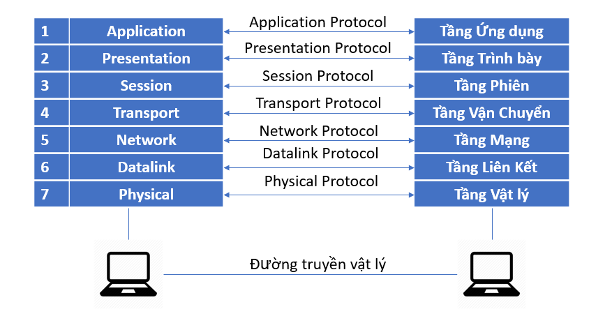
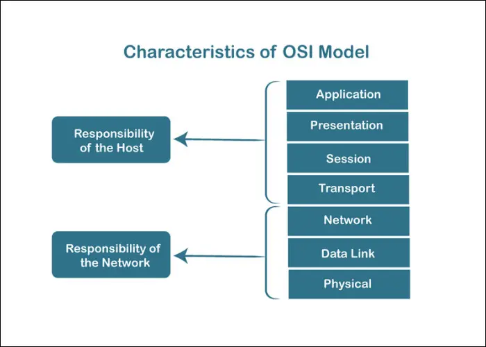
In the OSI model, the layers work closely together to ensure that data is transmitted accurately from the sending device to the receiving device. Each layer is responsible for a specific set of functions, but together they form a complete communication process.
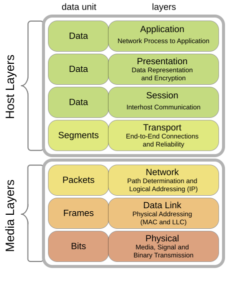
When data is sent, it moves downward through the layers following the encapsulation mechanism:
- The Application Layer creates the original data.
- The Presentation and Session Layers handle data formatting, encryption, and session establishment.
- The Transport Layer divides the data into segments and adds transmission control information.
- The Network Layer attaches IP addresses and converts segments into packets for routing across multiple networks.
- The Data Link Layer further encapsulates the data into frames with MAC addresses for transmission within the local network.
- Finally, the Physical Layer converts frames into electrical or optical signals and transmits them over cables or wireless media.
Illustration of data flow (top to bottom):
[Application Data] → [TCP Segment] → [IP Packet] → [Ethernet Frame] → [Bits on Wire]
When the data reaches the receiving device, the decapsulation process occurs in reverse: data travels from the Physical Layer up to the Application Layer, with each layer reading and removing its corresponding header in turn.
Understanding this mechanism helps us quickly identify the location of network issues.
4. The Role of the OSI Model in Learning and Practice
The OSI model is not merely a theoretical concept; it holds significant practical value in the field of computer networking and information technology.
- In education: The OSI model helps learners understand how networks operate through distinct layers, from the physical layer to the application layer. This functional separation makes the material easier to grasp, allowing students to clearly perceive the logic of data transmission and how different protocols interact with one another.
- In real-world network administration: Engineers use the OSI model as a “mental map” when troubleshooting network issues. For example, if there is a physical connectivity failure, they check Layer 1; if a device cannot be pinged, they examine Layer 3; if a website does not respond, they investigate Layer 7. This layered approach enables systematic fault isolation and more efficient problem resolution.
- In design and development: The OSI model serves as a common reference standard that helps hardware manufacturers, software developers, and protocol designers ensure interoperability and scalability across systems.
- In security: Each layer can implement its own protection mechanisms – such as data encryption at the Presentation layer, authentication at the Session layer, or firewalls at the Network layer – thereby enabling the construction of a multi-layered security architecture.
In summary, the OSI model functions as a standardized conceptual framework that supports learning, system design, troubleshooting, and security implementation in modern networking environments.
5. Conclusion
The OSI model is a fundamental conceptual framework in the field of computer networking. By dividing the communication system into seven independent layers, it enables a clearer understanding of how data moves, how protocols coordinate with one another, and how issues can be identified and resolved at specific functional layers. This layered structure reflects a modular design philosophy, in which each layer performs a distinct role while remaining tightly interconnected with the others to form a cohesive and complete system.
The greatest value of the OSI model does not lie in its direct implementation in real-world networks, but in the way it shapes how we think about and analyze networking systems. Thanks to this model, learning, teaching, protocol development, and network security can all be approached in a more systematic and logical manner.
Although today’s Internet primarily operates based on the TCP/IP model, the underlying principles of TCP/IP still reflect many concepts derived from OSI. From this perspective, the OSI model can be seen as a “foundational teacher,” while TCP/IP represents the practical application of those concepts, simplified and optimized for real-world deployment.
6. References
[1] A. S. Tanenbaum and D. J. Wetherall, Computer Networks, 6th ed. Pearson, 2011.
[2] J. F. Kurose and K. W. Ross, Computer Networking: A Top-Down Approach, 8th ed. Pearson, 2021.
[3] International Organization for Standardization, ISO/IEC 7498-1:1994 – Information technology — Open Systems Interconnection — Basic Reference Model: The Basic Model, ISO, 1994.
[4] G. M. Garner, Networking Essentials, 7th ed. Cengage Learning, 2020.
[5] IEEE Computer Society, IEEE Std 802.3-2018 — IEEE Standard for Ethernet, IEEE, 2018.